3 way Switch Troubleshooting & Diagrams
How complicated can 3 way switch troubleshooting be? Consider this. Since a 2-switch system has 3 wires to be connected to 3 terminals at each box, it works out that only 1 out of 9 possibilities will work. Each 4 way switch in-between would worsen the odds by a factor of 3. And any defective switch or connection further complicates things. What is going to be easier -- trial and error or understanding the 3 way switch system? ... (Or maybe calling an electrician in your area?)
Page Menu:
- Terminology and How a 3-Way System Works
- Generic 4-Way and 3-Way Switch Diagrams
- Wire Colors in a Multiple Switch System
- Standard 3-Way Switch Arrangement
- 3-Way Switch Variations
- Standard 4-Way Switch Arrangement
- 4-Way Switch Variations
- 3 Way Switch Troubleshooting
Terminology and How a 3-way System Works
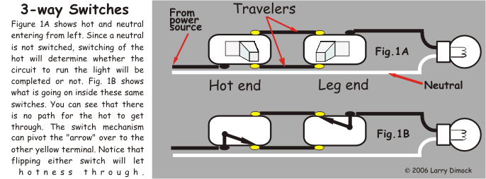
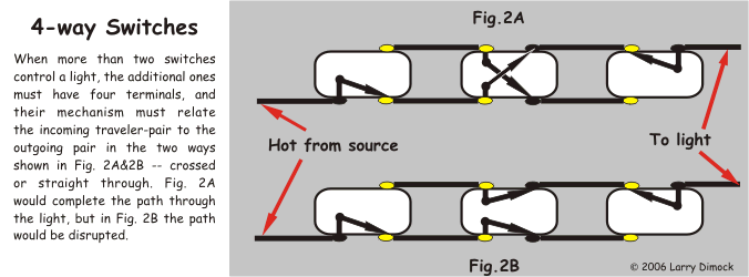
Multiple switches may be located at several approaches to a room in order to turn the room's lights on or off from any one of those locations. They do this by continuing hotness toward the light on two alternate paths -- wires called "travelers". Hotness (voltage) enters into the system at one "three-way" type switch, which we will call the "hot end." According to the position of its handle, hotness "travels" on to the next switch on one of the two traveler wires. If this next switch is the only other switch, it is also of the 3-way type and can be called the "leg end." It will pass the hotness on to the light(s), but only if its handle happens to be in the position that puts the light's wire in contact with the particular traveler that is bringing the hotness. Video. If there were any more switches between these two (electrically), they would simply pass hotness along but are able to change which traveler wire the power continues on; to do this, these (third, fourth, etc.) switches must be "four-way" type switches, a different animal than the first and last switches in the system. Four-way switches have four terminals to connect two traveler pairs to (the incoming pair and the outgoing pair). Three-way switches have three terminals, with the one that is not for the two travelers being called the "common". At the hot end, the incoming hot wire is connected to the common terminal. At the leg end the wire attached at the common is the one that goes to the light(s). This will all be made clear in the diagrams that follow.
The British perhaps use more common sense in naming these "2-way switches", but in North America we are stuck with more technical terms. I think I've noticed some Canadians and others talking about "tree-way switches". Anyway, I refer to these switches, wires, and the lights they control as a 3-way "system" not a 3-way "circuit", because that can be confused with the branch-circuit and breaker that such a system is part of.
Generic 4-way and 3-way Switch Diagrams
If you need to review what a circuit is or the function of a neutral wire, see Background. But here you see a diagram of the layout of 3-way switch wiring and what goes on inside the switches... In your mind, play with pivoting the contacts differently and notice that either switch is able to override what the other one did last.
 Between each switch box and the next, the travelers will both be contained in the same cable with each other. At most switch boxes there will be other wires serving other purposes -- one or two other wires in the travelers' cable itself and wires in other cables. Usually, but not always, the cable carrying the travelers has another insulated wire, which may be a neutral, a hot, or an extension of the leg wire (to the light). Occasionally a traveler cable will make its way to the next switch by running through the light box itself. The possibly strange routes these cables take and the various functions the non-traveler wires play does not change anything I have said here or will say. In simplest terms, every normal multi-switch system needs a neutral at the light box, a constant hot at one switchbox, travelers between it and the final switchbox (passing through any 4-way switches on the way), and a switched leg going from that final box to the light box. How this is all arranged in practice can vary greatly.
There are two abnormal and rare 3-way systems that may be encountered. They are called by various names (California, Hollywood, coast, farmer's, French, Chicago, Carter, lazy Susan, lazy neutral). The names are confused between the two kinds. One is illegal and presents possible shock danger. The other (British, I think) seems allowed by code and is so different in its concept that few electricians here would even recognize it. What I am saying about 3-way systems is not meant to apply to either of these. Basically, the illegal one attaches a hot permanently to one traveler and a neutral to the other; the commons each extend from their terminals to the light fixture. The legal one likewise attaches a hot to one traveler but the leg (to the light) to the other; another wire runs between the common terminals. Here is a diagram of these Rare 3-ways.
Since there is a wide variety of ways that multi-switch systems are wired in practice, I give, below, a number of 3-way and 4-way switch diagrams, so you can perhaps recognize your own version. To see some 3-ways in the context of a whole circuit, see the Typical circuit.
Wire Colors in a Multiple Switch System
I will try to describe here what color the insulation on the wires of multiple-switch systems will commonly be, if they are not miswired. Lately, Code is wanting any "factory" whites serving as travelers or as the hot-end hot to be re-marked black or red. Here I am only telling what you will commonly find in most homes. The hot wire at the common terminal of the hot-end switch will be black (or rarely: red or white). The light-leg wire at the common terminal of the leg-end switch will be black or (rarely) red. Each traveler pair is contained in one cable, and will be either black and white, black and red, or red and white. Most other white wires present in these switch boxes are neutrals that are connected to each other and not to any of the switch terminals. Any bare or green wires are grounding wires connected to each other. If the switch has an additional green screw, to meet Code a bare piece should be run to it from all the grounds.
The Standard 3-way Switch Arrangement
Normally encountered 3-way systems (3-way "circuits," as some call them) all share one scheme-theme:
--- S === S --- O
where the "S"s are the switches, the "O" is the light, and the lines shown are wires carrying constant (the line on the left) or switchable (the rest) hotness. The neutrals, not being involved in the switching operation, are not shown yet, since they can come into the picture in a variety of ways. Nor are boxes or cables containing the wires shown yet; nor any additional lights switched with the one shown; nor any 4-way switches, which would interrupt the path of the two traveler wires at any point. Above are two 3 way wiring diagrams of this scheme as you might see it in the flesh, complete with neutrals, boxes, and cables.
3-way Switch Variations
There are several common variations on this basic theme, which may look like deviations from it but are not. The main difference is that the following examples all have some of the switch-related wires spliced through boxes on their way to actually connecting to the light or switches. The wire colors shown in the switch diagrams below are not the only ones possible. They are some of what you may encounter, not necessarily how it should be done to current Code. These wiring schemes are often given names but the names are not consistent.A. Here the hot arrives at one switch box. It can then be connected through to the other switch to be its hot-all-the-time common, or instead it can attach as common of the switch where it arrived to begin with. Either way, the travelers between the switches end up giving hotness or unhotness to the light "leg." This leg either comes directly off the common of the switch nearest (electrically) to the light, or is tied through to the light from the switch furthest from it. This arrangement is a common one.
B. Here the hot for the system arrives at the light box, but its functional connection is at whichever switch it is connected through to. The other switch ends up sending the decision of the travelers back by way of the same cable that brought hotness down from the light box.
C. Here the travelers from one switch to the other are simply routed through the light box, where connectors pass them on through.
- The fact that house-cable comes with either two or three insulated conductors
- The physical relation (direction, order, distance) among the switches and lights
- The available sizes of electrical boxes to hold the wires, lights, and switches
- The direction from which the circuit is approaching the area
- The Code restrictions on how the cabling can be done
- The electrician's preferred tradition
The Standard 4-way Switch Arrangement
Normally encountered 4-way switch systems all share this scheme-theme:
--- S === S === S --- O
where the "S"s, the "O", and the lines are as described
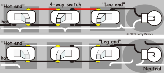
above. Here then are two ways you might see this basic scheme, complete with neutrals, boxes, and cables:

4-way Switch Variations
As you can see, this picture corresponds to the diagram for the basic 3-way switch system above. Many variations of this basic theme are possible. For instance, the 3-way switch schemes (A, B, C above) will allow a 4-way switch and box (or any number of them) to be interposed between the 3-way switch boxes. Then all three switches will work the light(s). Remember, one 3-way switch needs a constant hot, the other needs to be ready to "heat up" a wire to the light, a neutral needs to reach the light, and two travelers need to be passed between each switch in succession. Without taking up too much space, here are a few 4-way schemes in very simplified form, inspired by A, B, and C above:
--- S === S === S
|
O
--- O === S === S === S
--- S === S === O === S
--- S === O === S === S
--- O === S === S
|||
S
Next, as an example of more possibilities, I show a 4-way system in which the hot wire enters at the 4-way switch's box:

If you have begun to grasp the idea of 4-ways, you may be getting the impression that you could invent your own way to wire such a system. It is true. Whatever works, is not against Code, and is safe is possible. This site is not to advise you about design, Code, or installation.
3 way Switch Troubleshooting
Things that commonly cause a malfunction include:- One of the switches itself can fail.
- The connection of a wire at one of the switches can become loose. Both this and the previous problem can often be checked without disconnecting anything. With one prong of a neon tester in your hand, touch the other prong to the common terminal of each three way switch in turn. If one of those lights the tester up (is hot) regardless of all possible switch-positions of both switches, that is the hot end. Then just follow whether the next switch (even if it is a 4-way) is passing this hotness on through as expected, based on the diagrams above. Wherever it does not pass through is the bad connection or bad switch.
- Someone replacing a switch can do so incorrectly or can install a switch that only has two (non-green) terminals. Replacing a toggle-handle style switch with a large decorator style "rocker" switch can also invite a problem. The location of the terminals on the rocker is quite different. Here the foolproof way to connect is to have the travelers attach to the two same-color screws, and use the remaining common screw for the other wire.
- The two travelers are in the same cable with each other.
- Any pair of switch screws (or dimmer's wires) that are the same color as each other are for a traveler pair. Leviton's instructions for their rocker-style 4 way switch will confuse people by how they call one pair of terminals "IN" and one pair "OUT"; they have these identified backwards, but it doesn't even matter.
- The only wire in a multiple-switch system that is hot all the time when all the switches of the system are disconnected from their wires, is the hot. It will attach to the common terminal of the "hot end" switch.
Searchers who need to read the material on this page may be using phrases found in this statement: "When you replace a two way switch with a tree way switch, the 3 way electrical switch turns the 3 way circuit off."
"My husband disconnected several light switches without writing down how they were connected initially. Your youtube video about 3 way switches and home cicuit diagram were just what we needed to be able to figure out how to reconnect everything correctly." -Betsy
"Your site was instrumental in helping me reapair a previously mis-wired 3-way switch. I understood how they worked but didn't know what I was looking at until checking out your diagrams." -Shane